The assembler instructions: LOAD_A, input; LOAD_B, input; LOAD_C, input; LOAD_D, input are defined by the corresponding OPC values: 0001000; 00010001; 00010010; 00010011, where input is the 8-bit value on the input of the multiplexer in the data path (the C-bus) – consider this as an input port.
We will create a state machine that continuously will read the OPC from program memory and perform the corresponding above-mentioned operations in the XSMC. We draw the expected timing diagram for relevant signals, including the global clock and reset signals, before doing any VHDL design and we will explain the relation and timing considerations between the clock signal driving the data path and the clock signal driving the control part (state machine). As part of the solution, we create a simple IFU or integrate the IFU as part of the state machine.
library IEEE;
use IEEE.STD_LOGIC_1164.ALL;
use IEEE.STD_LOGIC_ARITH.ALL;
use IEEE.STD_LOGIC_UNSIGNED.ALL;
use IEEE.numeric_std.all;
entity state_mach is
Port ( clock : in STD_LOGIC;
OPC : in STD_LOGIC_VECTOR(7 DOWNTO 0);
reset : in STD_LOGIC;
Stout : out std_logic;
C1,C2 : out STD_LOGIC;
EN : in STD_LOGIC := '1';
loadA : out STD_LOGIC;
loadB : out STD_LOGIC;
loadC : out STD_LOGIC;
loadD : out STD_LOGIC;
enab_a1 : out STD_LOGIC;
enab_b1 : out STD_LOGIC;
enab_a2 : out STD_LOGIC;
enab_b2 : out STD_LOGIC;
enab_a3 : out STD_LOGIC;
enab_b3 : out STD_LOGIC;
enab_a4 : out STD_LOGIC;
enab_b4 : out STD_LOGIC;
enab_memory : out STD_LOGIC;
formemory: out std_logic_vector(4 downto 0));
end state_mach;
architecture Behavioral of state_mach is
type state_type is (st_base,st_loadA, st_loadB, st_loadC, st_loadD);
signal state, next_state : state_type;
begin
SYNC_PROC: process (clock)
variable counter, adress:std_logic_vector (4 downto 0) :="00000";
variable muxin : std_logic :='1';
begin
if (clock'event and clock = '0') then
if (reset = '1') then
state <= st_base;
counter :="00000";
formemory <= counter;
elsif (reset='0') then
state <= next_state;
case muxin is
when '1' =>
counter := counter + "00001";
formemory <= counter;
when others =>
formemory <= adress;
end case;
end if;
end if;
end process;
--MOORE State-Machine - Outputs based on state only
OUTPUT_DECODE: process (state)
begin
if state = st_base then
enab_memory <= EN;
loadA <= '0';
loadB <= '0';
loadC <= '0';
loadD <= '0';
enab_a1 <= '0';
enab_b1 <= '0';
enab_a2 <= '0';
enab_b2 <= '0';
enab_a3 <= '0';
enab_b3 <= '0';
enab_a4 <= '0';
enab_b4 <= '0';
C1 <= '0';
C2 <='0';
Stout <= '0';
elsif state = st_loadA then
enab_memory <= EN;
loadA <= '1';
loadB <= '0';
loadC <= '0';
loadD <= '0';
enab_a1 <= '0';
enab_b1 <= '1';
enab_a2 <= '0';
enab_b2 <= '0';
enab_a3 <= '0';
enab_b3 <= '0';
enab_a4 <= '0';
enab_b4 <= '0';
C1 <= '0';
C2 <='0';
Stout <= '1';
elsif state = st_loadB then
enab_memory <= EN;
loadA <= '0';
loadB <= '1';
loadC <= '0';
loadD <= '0';
enab_a1 <= '0';
enab_b1 <= '0';
enab_a2 <= '1';
enab_b2 <= '0';
enab_a3 <= '0';
enab_b3 <= '0';
enab_a4 <= '0';
enab_b4 <= '0';
C1 <= '0';
C2 <='1';
Stout <= '1';
elsif state = st_loadC then
enab_memory <= EN;
loadA <= '0';
loadB <= '0';
loadC <= '1';
loadD <= '0';
enab_a1 <= '0';
enab_b1 <= '0';
enab_a2 <= '0';
enab_b2 <= '0';
enab_a3 <= '0';
enab_b3 <= '1';
enab_a4 <= '0';
enab_b4 <= '0';
C1 <= '1';
C2 <='0';
Stout <= '1';
elsif state = st_loadD then
enab_memory <= EN;
loadA <= '0';
loadB <= '0';
loadC <= '0';
loadD <= '1';
enab_a1 <= '0';
enab_b1 <= '0';
enab_a2 <= '0';
enab_b2 <= '0';
enab_a3 <= '0';
enab_b3 <= '0';
enab_a4 <= '1';
enab_b4 <= '0';
C1 <= '1';
C2 <='1';
Stout <= '0';
end if;
end process;
NEXT_STATE_DECODE: process (state, OPC)
begin
next_state <= state;
case OPC is
when "00010100" =>
next_state <= st_base;
when "00010000" =>
next_state <= st_loadA;
when "00010001" =>
next_state <= st_loadB;
when "00010010" =>
next_state <= st_loadC;
when "00010011" =>
next_state <= st_loadD;
when others =>
next_state <= state;
end case;
end process;
end Behavioral;
Test Bench for State Machine
Begin
OPC <= "00010000";
reset <= '1';
EN <= '1';
wait for 10 ns;
OPC <= "00010001";
reset <= '0';
EN <= '1';
wait for 10 ns;
OPC <= "00010010";
reset <= '0';
EN <= '1';
wait for 10 ns;
OPC <= "00010011";
reset <= '0';
EN <= '1';
wait for 10 ns;
wait;
end process;
end;
Simulation Objects for State Machine test bench
Behavioral Simulation

Post Map Simulation

§ As we can see in the above program, we have five inputs (clock,OPC,reset, Cin and EN) and seventeen outputs (c1,c2,Stout,loadA, loadB, loadC, loadD,enab_a1, enab_b1, enab_a2, enab_b2, enab_a3, enab_b3, enab_a4, enab_b4,enab_memory and forememory) .
§ We have a signal of state_type which is assigned to state and next state.
§ We make use of simple counter which initializes memory by 1 so as to go to the next memory address after we have fetched an instruction.
§ We make a decode process so as to decode different values of LoadA,LoadB,LoadC and LoadD. Afterwards, we assigned the values to enab pins of different registers.
§ Next step is to define the conditions of how to get to the next state after the instructions for a particular state (Load) have been executed.
§ After this we make a test bench in which we enter the input values for four different cases.
§ Finally, we execute the test bench so as to get behavioral and post map simulation.
Program for the memory
library IEEE;
use IEEE.STD_LOGIC_1164.ALL;
use ieee.std_logic_unsigned.all;
entity memory is
Port ( clock : in STD_LOGIC;
EN : in std_logic;
ADDR : in std_logic_vector(4 downto 0);
DATA : out std_logic_vector(7 downto 0));
end memory;
architecture Behavioral of memory is
constant loada : std_logic_vector (7 downto 0) := "00010000";
constant loadb : std_logic_vector (7 downto 0) := "00010001";
constant loadc : std_logic_vector (7 downto 0) := "00010010";
constant loadd : std_logic_vector (7 downto 0) := "00010011";
type rom_type is array (7 downto 0) of std_logic_vector (7 downto 0);
signal ROM : rom_type:= (loada,loadb,loadc,loadd,"00010100","00010101","00010110","00010111");
signal rdata : std_logic_vector(7 downto 0);
begin
rdata <= ROM(conv_integer(ADDR));
process (clock)
begin
if (clock'event and clock = '1') then
if (EN = '1') then
DATA <= rdata;
end if;
end if;
end process;
end Behavioral;
Test bench for the memory
begin
wait for 10 ns;
EN <= '1';
ADDR <= "00001";
wait for 10 ns;
EN <= '0';
ADDR <= "00011";
wait for 10 ns;
EN <= '1';
ADDR <= "00010";
wait for 10 ns;
EN <= '1';
ADDR <="00101";
wait;
end process;
END;
Simulation Objects for memory
Behavioral simulation

Post Map simulation

Explanation:
· For our memory program we make use of ROM model of memory.
· In the entity we initialize a 5 bit memory address called ADDR, a memory enable(EN) and an eight bit output called DATA.
· In the architecture part we assign particular values to loadA, loadB, loadC and loadD which are defined as constants .
· As according to our requirements we define a memory array of eight elements and each element being of eight bits.
· We define two signals , the first one called ROM is used for holding the values of loadA, loadB, loadC and loadD and the other called rdata is of eight bits is used for taking values from memory addresses.
· In the process we introduce the rising edge of the clock so as to synchronize the process and then we check if EN is enabled (value =1). If yes, then the value from rdata is passed on to DATA for output.

Final schematic test bench
BEGIN
SELEC <= '1';
Cin <= "00010000";
EN <= '1';
RESET <= '1';
wait for 50 ns;
SELEC <= '0';
Cin <= "00010110";
EN <= '0';
RESET <= '0';
wait for 100 ns;
SELEC <= '1';
Cin <= "10101000";
EN <= '1';
RESET <= '0';
wait for 150 ns;
SELEC <= '1';
Cin <= "00000000";
EN <= '0';
RESET <= '1';
wait for 300 ns;
WAIT; -- will wait forever
END PROCESS;
END;
Simulation Objects for schematic
Behavioral Simulation

Post Map Simulation
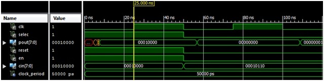
Explanation:
For the final schematic we connected various functional blocks together.
We connected memory to the state machine by connecting the memory address to the for memory and the value fetched by instruction fetch unit to the OPC as input.
We also connected an enable signal as output to the state machine so that passing of memory addresses is enabled.
We connected the various outputs like loads and enables their respective registers.
We introduce two control outputs in the state machine which are used to select different operations of ALU.
Then we created a suitable test bench for the final schematic and executed it to get behavioral and post map simulations.
No comments:
Post a Comment